Designing A Mother's Day Electronic Gift

For Mother's Day this year I decided to design a mantel-piece gift for my mum with embedded electronics. With the right tools, going from design to finished product can be quick and fun!
The Moon Bunny
The gift I designed was a remix ofJukka Seppänen's Moon Bunny from MyMiniFactory.


When coming up with ideas for a gift my first thought was to look for some kind of rabbit, as my mother is extremely fond of bunnies. Browsing Thingiverse and MyMiniFactory for ideas, I stumbled upon the Moon Bunny design. It's simple, cute, and easy to work with. My concept was to take that model as my foundation, create an elegant-looking base for it, paint it to look polished, and add some kind of lights or music to really transform a static display piece into something more.
In order to design the base, I took the model and imported it into Fusion 360. Fusion is a great tool for projects like this- it's free for Hobbyists making less than $100k/yr and designing a model in CAD is a fairly intuitive process of sketching, extruding, and modifying shapes until you're left with your final object.

Designing the Base
I began by making a quick sketch of the base, trying to make sure that it would be wide enough to give a good stable footprint so the model would sit nicely without being easily knocked over, as well as large enough overall to look like a nice big stand. This would also provide me with plenty of space to put any electronics inside that I desired.

Tweaking Shapes
Once I had extruded the base downwards far enough to give me plenty of room for electronics and to add text to the front, I started tweaking my shapes to make the stand into something more elegant than a simple box. I added a heavy chamfer to create the back corners, providing a more sleek appearance, and then I added fillets to all the vertical edges*. Lastly, I added another chamfer to the top edge to give the overall design a beveled chiseled marble appearance (I knew I would be printing with a marble effect PLA, so I was embracing that aesthetic). At this point I also used the "Shell" feature in Fusion to hollow out the base. This was done for several reasons: 1) to reduce the printing time, 2) to save on materials, and 3) to provide room for electronics to be stuffed inside later. I chose a 2mm thickness for this wall, which would be printed solid with the number of perimeters I would be using on my 0.4mm nozzle; 2-3mm thick walls I've found to be sufficiently sturdy for most purposes.
* When using Fillets in a 3D print, you want to consider how your print orientation will affect the appearance. If you add Fillets on the X/Y plane your toolhead can follow those contours nicely, giving you a nice smooth rounded corner. Attempting to add horizontal Fillets, however, can produce less optimal results, as the stair-stepping in your Z-Axis can make rounded details look stochastic rather than smooth. The changing curvature can also introduce problems for Fillets on overhangs because the first few layers are trying to extend outward quickly, without good support from the layers below them. For horizontal cuts, I prefer Chamfers because the constant 45° cut makes printing results much better.

Adding the Text
My next step was to add the text to the front face of the base. For this, I opened up Adobe Illustrator**, picked out a font I liked, and arranged my text there. When picking my font I tried to pick a fairly rigid monolithic font, rather than a stylized or hand-written font. The reasoning was two-fold- firstly, it suited my chiseled marble art style to go with a bold monolithic font; secondly, because I knew this font would need to be printed in FDM I wanted a font that wasn't very curvy, but instead had lots of straight lines and consistent angles. Straight horizontal and vertical lines would be easily printed without the stair-stepping in the Z-Axis affecting the resolution and quality of the result.
** I chose to create my text in Adobe Illustrator because I could import it as an SVG outline into a Fusion Sketch to easily extrude the profiles- Fusion's built-in text tool is a little bit finicky and problematic, so its easier to create text externally and import it into a sketch. Inkscape could also be used as a free alternative to Illustrator.

Panel Mount Button
My next step was to cut out a hole in the side of the housing to allow me to press a panel-mount button into the stand. This would act as the trigger switch for whatever electronics I decided to go with. At this point I was still debating if I wanted to add lights or sounds, but having a hole for a button would allow me to set up either option.
Panel-mount buttons are quickly becoming my favourite for electronics projects. Their ease of installation makes it so much easier to integrate them into designs, without having to come up with other methods for mounting such as specially designed snap slots or room for screws to be tapped- all you need is a hole to put the button through and its own locking nut does the rest.

Power Cable Hole
My last step for designing this base was to cut a notch in the back for the power cable to run through. The way I usually add these is to add a center-point circle at the mid-point of the bottom edge of the face I want to punch through, and create a hole that is 10-15mm in diameter. Because half the circle will be below the bottom edge, it will be lost, so the actual notch we are cutting will be 5-7.5mm wide/tall. Most power cables you will use will be smaller than that, so this works great. But you definitely want to cut a notch for the power cable to run through (unless you're using batteries and don't need an external power cable) so that your finished design can sit flush rather than being wedged upwards by the cord.

Boolean Difference
At this point I exported an STL from Fusion 360 of my completed base stand design, and I took the model along with the model of the Moon into Blender 3D. Blender 3D is a free & open source 3D modeling/sculpting/animating/etc... software. It is incredibly powerful, and feature comparable to big-name software like Autodesk 3DS Max or Maya. In this case, what I wanted to do was to cut a hole in the top of the stand that the rim at the bottom of the Moon would sit inside so they could be glued together in alignment. This step couldn't be done in Fusion 360 because you cannot perform combine operations between Meshes and Solid Bodies. So, I simply moved the Moon's bottom into place centered up to the Base Stand, moved it down until it was just poking through the thickness of the hollowed shell of the model, and then performed a boolean difference to remove the overlapping area, leaving me with a nice form-fitting hole that the moon would rest in.

Prepping to Print
For printing, I used Simplify3D as my slicer. I import the model of the base stand, and using the "Place Surface On Bed" command I select one of the faces on the top of my model to touch the build plate. This means my model will print upside down, but I also designed with this intentionally in mind, because this print orientation means I have no unsupported overhangs*** and will not need to use any support material for printing.
*** Some people may notice that there is a hole in the side for the panel-mount button which is technically an unsupported overhang, as well as the letters of the text on the face. In regards to the hole for the panel mount button, the hole is not unsupported because the circle comes back together to meet at the top- the overhang is actually supported on both sides, and the amount of bridging to complete the top is minimal. As for the text on the face, yes this is all technically unsupported, but the text only protrudes 1mm from the face of the model. This detail will be small enough and cool quickly enough that it will not sag significantly at all, and does not need supports to remain crisp.
Painted and Assembled
I transfer my GCode to an SD card, stick that in my Prusa MK3S, and by the next day, my models are complete. Once my parts are done printing, I go ahead and begin painting.
For the Spring Bunny itself, I begin with an undercoat of black. I know that I want the final model to look like a cast statue, so starting with black gives a nice base for metallics to shine over, and in the crevices and corners where I struggle to paint my metal finish, the black will simply appear as a dark shaded recess. After I my undercoat has dried, I take some Rub n' Buff which is a really useful wax-based grease used for restoring furniture with a metallic shine, and begin wiping that with a cloth all over the surface of the rabbit. This quickly gives the bunny a realistic metallic finish that makes it look like a real cast piece. This easily passes the "3ft Test" as a convincing cast metal object.
Next, I get to work on the Moon. I begin with a base coat of grey. This I apply in two thin coats of acrylic paint. When painting models, you always want to apply several thin coats, rather than single thick coats. This makes drying quicker, avoids paint clogging up and obscuring the details, and avoids the risk of dripping and puddles. Once my base coats have finished drying, I take a stiff-bristle brush and apply white paint to it, and then wipe most of that off in a paper towel. This leaves me with just a small amount of paint still captured in the bristles, which I will then use to lightly brush over the surface and edges of my model. This paint will lightly dust the surface, catching primarily on raised details and edges. This technique is called "dry brushing" and helps to create highlights and distress marks on raised surfaces. Once I'm done with this step, I finish by doing a wet wash of black acrylic. I take a wet sponge brush dipped in black paint and wipe this all over my model, and then quickly take a paper towel to clean off as much of it as I can. This process removes most of the dark tone from the top surfaces (albeit staining them down a little bit) but leaves behind the black paint in the crevices and holes that are not easily reached by the towel. This leaves darkness in all those recesses where you would expect there to be shadows or built-up dirt & grunge. This wash helps add contrast, and combined with our dry-brushed highlights really makes the details on the model pop.
For the base stand, I used a marble-effect PLA, so I don't want to ruin that surface. For this, I take a small detail brush with some gold paint and in a few thin coats, I go over the lettering on the surface to really make it pop.
For learning painting techniques, there's a few resources I love- first are prop artists like Adam Savage's Tested or Punished Props Academy. Second is actually the Warhammer miniature model painting tutorials from Games Workshop, where they go over techniques for making small details pop on little models.

Electronics
My last step is to install the electronics. I finally decided on adding a short "ringtone" of music that plays at the push of the button. For this, I had lying around on hand a number of Adafruit components. First was their SFX board with integrated drivers, second was their Mini Metal Speaker, and third was a 2000mAh LiPo battery. Adafruit parts can be somewhat expensive, but the convenience of having access to all their guides and resources of information, as well as knowing that all their parts are specially picked out to work together on the LiPo's with JST connectors makes them valuable. Having a pile of Adafruit components lying around means that when I do one-day-build projects like this I know everything is going to work together, and if I ever get stumped or need information I know I will have data sheets and tutorials available to me. In particular, I really like their SFX Chip, because you can plug it directly into your computer as if it were a USB memory stick, and copy your sound files directly onto it. The chip also comes with a number of functions for playing back different sounds for different buttons or doing loops and other features, all based on the naming conventions of the sound files, which makes things really easy to set up.
As far as wiring goes, it's very simple. The SFX chip has the JST connector soldered onto the back, so the battery just plugs in. The panel-mount button I'm using has a 3v LED inside, and 4 pins- 2 pins are the +/- terminals for the LED, and the other 2 pins are the switch's +/- terminals (consult the data sheet if you need clarification on distinguishing the terminals on your buttons). Because I know my LiPo will provide approximately 4.2-3.7v of power; I add a 100Ω resistor into the wire for the LED (+) terminal. I then connect the (+) terminal to the Vin pin on my SFX chip, so it can take power from the battery, and connect the (-) terminal to the GND to complete the circuit. Then, in order to trigger my "ringtone" I connect the other two terminals to the pin0 and GND on the other side of the board- the board triggers sounds when any of the pins are connected to ground.
Connecting the speaker is super simple, you loosen the screws at the top of the terminal block, shove in the speaker wires, and clamp them in place with the screws. And that's all it takes!
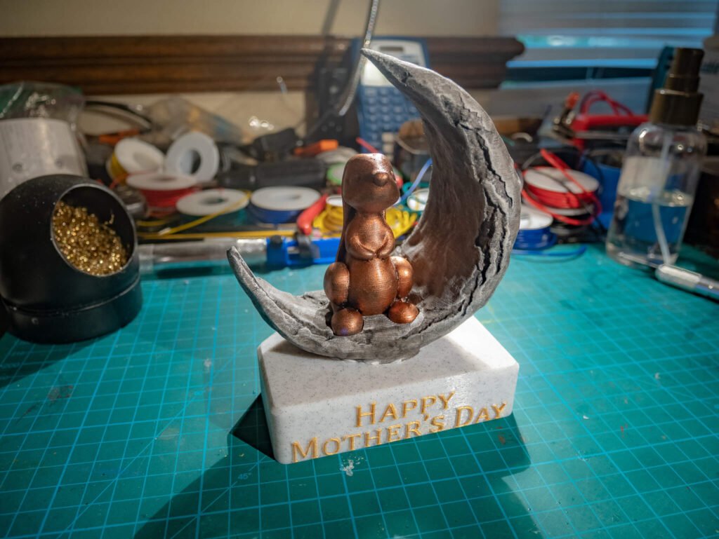
Completed Moon Bunny!
And that's it, my Mother's Day gift is now complete. The ring on my button lights up, and when you press it, it triggers a short "ringtone" that I dropped onto it from my PC.